Year of production: 2011
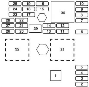
Floor console fuse block
The floor console fuse block is located on the passenger side of the floor console behind the forward panel. The panel has four clips, one in each corner.
| Fuses | Description |
| 1 | Fuse Puller |
| 2 | Empty |
| 3 | Empty |
| 4 | Empty |
| 5 | Empty |
| 6 | Amplifier |
| 7 | Cluster |
| 8 | Ignition Switch, PASS-Key® III+ |
| 9 | Stoplamp |
| 10 | Heating, Ventilation, Air Conditioning, PASS-Key® III+ |
| 11 | Empty |
| 12 | Empty |
| 13 | Airbag |
| 14 | Empty |
| 15 | Windshield Wiper |
| 16 | Climate Control System, Ignition, Rear View Camera |
| 17 | Power Windows |
| 18 | Empty |
| 19 | Electric Power Steering, Steering Wheel Control |
| 20 | Sunroof |
| 21 | Empty |
| 22 | Empty |
| 23 | Audio System |
| 24 | XM Radio™, OnStar™ |
| 25 | Engine Control Module, Transmission Control Module |
| 26 | Door Locks |
| 27 | Interior Lights |
| 28 | Steering Wheel Control Illumination |
| 29 | Empty |
| Relays | Usage |
| 30 | Climate Control System |
| 31 | Empty |
| 32 | Retained Accessory Power (RAP) |
Engine compartment fuse block
The underhood fuse block is located on the driver side of the engine compartment.
| Fuses | Description |
| 1 | Electric Power Steering |
| 2 | Rear Defogger |
| 3 | Empty |
| 4 | Body Control Module 3 |
| 5 | Starting System |
| 6 | Body Control Module 2 |
| 7 | Rear Power Plug (Panel Van Only) |
| 8 | Empty |
| 9 | Air Conditioning Clutch Diode |
| 10 | Liftgate, Sunroof |
| 11 | Empty |
| 12 | Rear Power Outlet (Panel Van Only) |
| 13 | Fuel Pump |
| 20 | Rear Wiper |
| 21 | Mirror |
| 22 | Air Conditioning |
| 23 | Heated Seats (Option) |
| 25 | Fuse Puller |
| 27 | Empty |
| 29 | Cigarette Lighter |
| 30 | Power Outlet |
| 31 | Daytime Running Lamps |
| 32 | Empty |
| 33 | Emissions |
| 36 | Power Windows |
| 37 | Power Seat (Option) |
| 40 | Cooling Fan |
| 41 | Engine Control Module |
| 42 | Empty |
| 43 | Engine Control Module, Transmission |
| 44 | Antilock Brake System (Option) |
| 45 | Injectors, Ignition Module |
| 46 | Backup Lamps |
| 47 | Heated Seat |
| 49 | Windshield Washer Pump |
| 53 | Fog Lamps (Option) |
| 56 | Sensing and Diagnostic Module (SDM) |
| 57 | Antilock Brake System (Option) |
| 58 | Windshield Wiper Diode |
| 59 | Windshield Wiper |
| 60 | Horn |
| 61 | Antilock Brake System (Option) |
| 62 | Instrument Panel, Ignition |
| 63 | Driver Side High-Beam |
| 64 | Canister Vent |
| 65 | Driver Side Low-Beam |
| 66 | Passenger Side Low-Beam |
| 67 | Passenger Side High-Beam |
| 69 | Parking Lamps |
| Relays | Description |
| 14 | Rear Defogger Relay |
| 15 | Air Conditioning Clutch |
| 16 | Empty |
| 17 | Rear Wiper |
| 18 | Liftgate Release |
| 19 | Fuel Pump |
| 24 | Empty |
| 26 | Powertrain |
| 28 | Daytime Running Lamps |
| 34 | Starting System |
| 35 | Empty |
| 38 | Empty |
| 39 | Windshield Washer Pump |
| 48 | Rear Windshield Washer |
| 50 | Cooling Fan |
| 51 | Run, Crank |
| 52 | Windshield Wiper |
| 54 | Fog Lamps (Option) |
| 55 | Horn |
| 68 | Parking Lamps |
| 70 | Windshield Wipers |
| 71 | Headlamp Low-Beam |
| 72 | Headlamp High-Beam |
WARNING: Terminal and harness assignments for individual connectors will vary depending on vehicle equipment level, model, and market.


