Opel Meriva B (2012 – 2016) – fuse box diagram
Years: 2012, 2013, 2014, 2015, 2016
Engine compartment fuse box
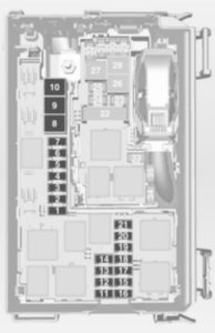
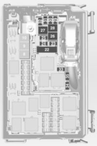
The fuse box is in the front left of the engine compartment.
| Number | Circuit |
| 1 | Starter |
| 2 | — |
| 3 | Fuel filter, cooling |
| 4 | Horn |
| 5 | Terminal 30 |
| 6 | Engine control module, transmission control unit |
| 7 | Fog light |
| 8 | Engine cooling |
| 9 | Engine cooling |
| 10 | Vacuum pump |
| 11 | Ignition, preheating |
| 12 | Headlamp levelling |
| 13 | Air conditioning system, terminal 15 |
| 14 | Transmission control unit |
| 15 | High beam right |
| 16 | High beam left |
| 17 | Engine control module |
| 18 | Engine control module, terminal 15 |
| 19 | Airbag |
| 20 | Engine control module |
| 21 | Engine control module, terminal 87 |
| 22 | Electrical parking brake |
| 23 | Tyre repair kit |
| 24 | Fuel pump |
| 25 | ABS |
| 26 | Heated rear window |
| 27 | ABS |
| 28 | Interior fan |
| 29 | Cigarette lighter |
| 30 | Air conditioning system |
| 31 | Front power window, left |
| 32 | Front power window, right |
| 33 | Mirror heating |
| 34 | ABS |
| 35 | Airbag |
Instrument panel fuse box
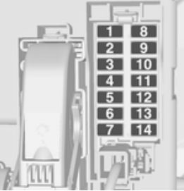
The fuse box is behind the storage compartment in the instrument panel. Open compartment, compress the locking tabs, fold compartment down and remove.
In right-hand drive vehicles, the fuse box is located behind a cover in the glovebox. Open the glovebox, pull cover upwards and remove.
| Number | Circuit |
| 1 | Radio |
| 2 | Display, instrument, telephone |
| 3 | Radio |
| 4 | Ignition switch, immobiliser |
| 5 | Windscreen washer, rear screen washer |
| 6 | Central locking system, tailgate |
| 7 | Central locking system |
| 8 | Display, instrument, telephone |
| 9 | Heated steering wheel |
| 10 | Rear left door unlocking |
| 11 | Rear right door unlocking |
| 12 | Courtesy light |
| 13 | Rain sensor, interior mirror, outside mirrors |
| 14 | — |
Load compartment fuse box
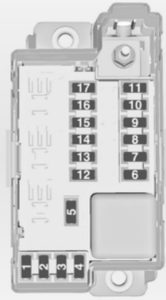
The fuse box is on the left side of the load compartment behind a cover. Remove the cover.
Disengage the four retaining lugs and remove the cover.
| Number | Circuit |
| 1 | Adaptive forward lighting |
| 2 | — |
| 3 | — |
| 4 | — |
| 5 | — |
| 6 | Rear power window, right |
| 7 | Adaptive forward lighting |
| 8 | Trailer module, Trailer socket |
| 9 | Seat, lumbar support, left |
| 10 | Rear power window, left |
| 11 | Park assist |
| 12 | Electrical sunblind |
| 13 | — |
| 14 | Heated front seats |
| 15 | Trailer module |
| 16 | Seat, lumbar support, right |
| 17 | — |
WARNING: Terminal and harness assignments for individual connectors will vary depending on vehicle equipment level, model, and market.


