Audi A4 (2017) – fuse box diagram
Year of production: 2017
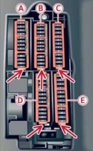
Fuse assignment – driver’s/front passenger’s footwell

Front passenger ‘s footwell (right -hand drive vehicle)

Fuse panel A (brown)
| Number | Electric equipment |
| 1 | — |
| 2 | Mass airflow sensor, camshaft adjustment |
| 3 | Exhaust doors, fuel injectors, radiator inlet |
| 4 | Vacuum pump, hot water pump, particulate sensor, biodiesel sensor |
| 5 | Brake light sensor |
| 6 | Engine valves |
| 7 | Heated oxygen sensor, mass airflow sensor |
| 8 | Water pump, high pressure pump, high pressure regulator valve |
| 9 | Hot water pump |
| 10 | Oil pressure sensor, oil temperature sensor |
| 11 | Clutch pedal position sensor |
| 12 | Engine valves |
| 13 | Radiator fan |
| 14 | Fuel injectors |
| 15 | Ignition coils |
| 16 | Fuel pump |
Fuse panel B (red)
| Number | Electric equipment |
| 1 | Anti-theft alarm system |
| 2 | Engine control module |
| 3 | Lumbar support |
| 4 | Automatic transmission selector mechanism |
| 5 | Horn |
| 6 | Electromechan ical park ing brake |
| 7 | Gateway control module |
| 8 | Interior headl iner lights |
| 9 | — |
| 10 | Airbag control module |
| 11 | Electronic Stabilization Control (ESC |
| 12 | Diagnostic connector, light/rain sensor |
| 13 | Climate control system |
| 14 | Right front door control module |
| 15 | A/C compressor |
Fuse panel C (black)
| Number | Electric equipment |
| 1 | Front seat heating |
| 2 | Windshield wipers |
| 3 | Left head light electronics |
| 4 | Panorama glass roof/ sliding/t ilting sunroof |
| 5 | Left front door control module |
| 6 | Sockets |
| 7 | Right rear door control module |
| 8 | — |
| 9 | Right headlight electronics |
| 10 | Windshield washer system/headlight washer system |
| 11 | Left rear door control module |
Fuse panel D (black)
| Number | Electric equipment |
| 1 | Seat ventilation, rearv iew mirror, rear climate control system controls |
| 2 | Gateway, climate control system |
| 3 | Sound actuator/exhaust sound tuning |
| 4 | Clutch pedal position sensor |
| 5 | Engine start |
| 6 | — |
| 7 | — |
| 8 | Homelink |
| 9 | Adaptive cruise control |
| 10 | — |
| 11 | Video camera |
| 12 | Matrix LED headlight/right LED headlight |
| 13 | Matrix LED headlight/left LED headlight |
| 14 | Rear window wiper |
Fuse panel E (red)
| Number | Electric equipment |
| 1 | Ignition coils |
| 2 | Natural gas tank valves |
| 3 | — |
| 4 | — |
| 5 | Engine mount |
| 6 | Automat ic transmission |
| 7 | Instrument panel |
| 8 | Climate control system (blower) |
| 9 | — |
| 10 | Dynamic steering |
| 11 | Engine start |
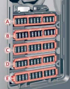
Driver’s side cockpit fuse assignment

| Number | Electric equipment |
| 1 | — |
| 2 | Telephone |
| 3 | — |
| 4 | Head-up display |
| 5 | Audi music interface |
| 6 | Front climate control system controls |
| 7 | Steering column lock |
| 8 | Infotainment syst em display |
| 9 | Instrument cluster |
| 10 | Infotainment unit |
| 11 | Light switch |
| 12 | Steering column electronics |
| 13 | — |
| 14 | Infotainment system |
| 15 | — |
| 16 | Steering wheel heating |
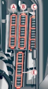
Left luggage compartment fuse assignment

Fuse panel A (black)
| Number | Electric equipment |
| 1 | — |
| 2 | Windshield defroster |
| 3 | Windshield defroster |
| 4 | — |
| 5 | Suspension control |
| 6 | Automatic transmission |
| 7 | Rear window defogger |
| 8 | Rear seat heating |
| 9 | Tail lights |
| 10 | Left safety belt tensioner |
| 11 | Central locking |
| 12 | Electric luggage compartment lid |
Fuse panel B (red)
| Number | Electric equipment |
| Not assigned |
Fuse panel C (brown)
| Number | Electric equipment |
| 1 | — |
| 2 | Telephone |
| 3 | Lumbar support |
| 4 | Audi side assist |
| 5 | — |
| 6 | — |
| 7 | — |
| 8 | — |
| 9 | — |
| 10 | — |
| 11 | — |
| 12 | Homelink |
| 13 | Rearview camera, peripheral cameras |
| 14 | Right tail lights |
| 15 | — |
| 16 | Right safety belt tensioner |
Fuse panel E (red)
| Number | Electric equipment |
| 1 | — |
| 2 | Sound-amplifier |
| 3 | AdBlue |
| 4 | — |
| 5 | Trailer hitch (right light) |
| 6 | — |
| 7 | Trailer hitch |
| 8 | Trailer hitch (left light) |
| 9 | Trailer hitch (socket) |
| 10 | Sport differential |
| 11 | Ad Blue |
WARNING: Terminal and harness assignments for individual connectors will vary depending on vehicle equipment level, model, and market.


