Chery J1 (2007 – 2015) – fuse box diagram
Year of production: 2007, 2008, 2009, 2010, 2011, 2012, 2013, 2014, 2015
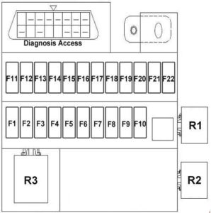
The instrument panel fuse panel
| No. |
A |
Function/component |
| F1 | 10 | Combined instruments |
| F2 | 10 | Rear view mirror, brake switch, BCM |
| F3 | 10 | ABS control |
| F4 | 10 | Air Bag |
| F5 | – | Not used |
| F6 | 15 | Washer, rear wiper power supply, sunroof control |
| F7 | 10 | Steering power supply, A/C relay coil |
| F8 | 15 | Front wiper |
| F9 | 15 | Cigarette lighter |
| F10 | 10 | Radio/player control |
| F11 | – | Not used |
| F12 | 25 | Start |
| F13 | 10 | Diagnosis Access |
| F14 | 10 | Braking Lamp |
| F15 | 20 | Audio device |
| F16 | 15 | Horn, fog lamp |
| F17 | – | Not used |
| F18 | 10 | Clearance lamp, ceiling lamp |
| F19 | 15 | Alarm switch |
| F20 | 10 | Lamp switch, instrument |
| F21 | 20 | Sunroof power supply |
| F22 | 20 | Rear Defroster |
| Relay | ||
| R1 | Blower Relay | |
| R2 | Steering relay | |
| R3 | Front wiper relay | |
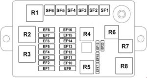
Engine compartment fuse box
| No. |
A |
Function/component |
| SF1 | 30 | Fan. high speed |
| SF2 | 30 | BCM |
| SF3 | 30 | A/C |
| SF4 | 40 | Instrument electric |
| SF5 | 30 | ABS |
| SF6 | 30 | ABS |
| EF1 | 20 | Fan. low speed |
| EF2 | 15 | Front fog lamp |
| EF3 | 10 | ECU |
| EF4 | 15 | Fuel pump |
| EF5 | 30 | Primary relay |
| EF6 | 10 | Compressor |
| EF7 | 15 | Oxygen sensor |
| EF8 | – | Not used |
| EF9 | 15 | Ignition coil |
| EF10 | 10 | Backup lamp |
| EF11 | 10 | Right position lamp |
| EF12 | 10 | Left position lamp |
| EF13 | 10 | Right high beam |
| EF14 | 10 | Left high beam |
| EF15 | 10 | Right low beam |
| EF16 | 10 | Left low beam |
| EF17 | 10 | Spare |
| EF18 | 10 | Spare |
| EF19 | 10 | Spare |
| EF20 | 10 | Spare |
| Relay | ||
| R1 | Front Fog Lamp Relay | |
| R2 | Fan High-Speed Relay | |
| R3 | Fan Low-Speed Relay | |
| R4 | Low Beam Relay | |
| R5 | Compressor | |
| R6 | High Beam Relay | |
| R7 | Main relay | |
| R8 | Electric Fuel Pump | |
WARNING: Terminal and harness assignments for individual connectors will vary depending on vehicle equipment level, model, and market.


