Year of production: 2006
Instrument Panel Fuse Block
The fuse block access door is on the driver’s side edge of the instrument panel.
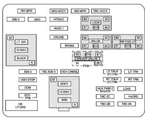
| Name | Usage |
| RR Wiper | Not Used |
| SEO ACCY | Special Equipment Option Accessory |
| WS WPR | Windshield Wipers |
| TBC ACCY | Truck Body Controller Accessory |
| IGN 3 | Ignition, Heated Seats |
| 4WD | Four-Wheel Drive System |
| HTR A/C | Climate Control System |
| LCK | Power Door Lock Relay (Lock Function) |
| HVAC 1 | Inside Rearview Mirror, Climate Control System |
| LT DR | Driver’s Door Harness Connection |
| CRUISE | Cruise Control |
| UNLOCK | Power Door Lock Relay (Unlock Function) |
| RR FOG LP | Rear Fog Lamp (Export Only) |
| BRAKE | Anti-Lock Brake System |
| DRIVER UNLOCK | Power Door Lock Relay (Driver’s Door Unlock Function) |
| IGN 0 | Powertrain Control Module, Transmission Control Module |
| TBC IGN 0 | Truck Body Controller |
| VEH CHMSL | Vehicle and Trailer High Mounted Stoplamp |
| LT TRLR ST/TRN | Left Turn Signal/Stop Trailer |
| LT TRN | Left Turn Signals and Sidemarkers |
| VEH STOP | Vehicle Stoplamps, Brake Module, Electronic Throttle Control Module |
| BODY | Harness Connector |
| RT TRLR ST/TRN | Right Turn Signal/Stop Trailer |
| RT TRN | Right Turn Signals and Sidemarkers |
| DDM | Driver Door Module |
| AUX PWR 2, M/GATE | Rear Cargo Area Power Outlets, Midgate |
| LCKS | Power Door Lock System |
| ECC, TPM | Rear Electronic Climate Control, Tire Pressure Monitoring System (If Equipped) |
| TBC 2C | Truck Body Controller |
| HAZRD | Flasher Module |
| CB LT DRS | Left Power Window Circuit Breaker |
| TBC 2B | Truck Body Controller |
| TBC 2A | Truck Body Controller |
Center instrument panel utility block
The center instrument panel utility block is located underneath the instrument panel, to the left of the steering column.
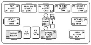
| Relay name | Usage |
| SEO | Special Equipment Option/Off-road Lamps Harness Connector |
| TRAILER | Trailer Brake Wiring |
| UPFIT | Upfitter (Not Used) |
| SL RIDE | Ride Control (Not Used) |
| HDLR 2 | Headliner Wiring Connector 2 |
| BODY | Body Wiring Connector |
| DEFOG | Rear Defogger Relay |
| HDLNR 1 | Headliner Wiring Connector 1 |
| SPARE RELAY | Not Used |
| CB SEAT | Driver and Passenger Seat Module Circuit Breaker |
| CB RT DOOR | Rear Right Power Window, Passenger Door Module |
| SPARE | Not Used |
| INFO | Not Used |
Underhood fuse block
The underhood fuse block is located near the battery on the driver’s side of the vehicle.
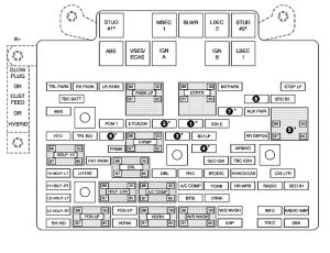
*1 — Gasoline Engine and Fuel Injection Rail #2.
*2 — Gasoline Engine and Fuel Injection Rail #1.
*3 — Gasoline Engine; Oxygen Sensors.
*4 — Gasoline Engine; Oxygen Sensors.
*5 — Ignition 1
*6 — Powertrain Control Module, Fuel Pump.
*7 — Rear Climate Control.
*8 — Sunroof
| Fuse | Usage |
| GLOW PLUG | Not Used |
| CUST FEED | Accessory Power |
| HYBRID | Not Used |
| STUD #1 | Auxiliary Power |
| MBEC | Mid Bussed Electrical Center Power Feed, Front Seats, Right Doors |
| BLOWER | Front Climate Control Fan |
| LBEC | Left Bussed Electrical Center, Door Modules, Door Locks, Auxiliary Power Outlet—Rear Cargo Area and Instrument Panel |
| STUD #2* | Accessory Power/Trailer Wiring Brake Feed |
| ABS | Anti-Lock Brakes |
| VSES/ECAS | Automatic Level Control (ALC) Compressor |
| IGN A | Ignition Power |
| IGN B | Ignition Power |
| LBEC 1 | Left Bussed Electrical Center, Left Doors, Truck Body Controller, Flasher Module |
| TRL PARK | Parking Lamps Trailer Wiring |
| RR PARK | Right Rear Parking and Sidemarker Lamps |
| LR PARK | Left Rear Parking and Sidemarker Lamps |
| PARK LP | Parking Lamps Relay |
| STRTR | Starter Relay |
| INTPARK | Interior Lamps |
| STOP LP | Stoplamps |
| TBC BATT | Truck Body Controller Battery Feed |
| SEO B2 | Off-Road Lamps |
| 4WS | Vent Solenoid Canister/Quadrasteer Module Power |
| AUX PWR | Accessory Power Outlet — Console |
| PCM 1 | Powertrain Control Module |
| ETC/ECM | Electronic Throttle Control, Electronic Brake Controller |
| IGN E | Instrument Panel Cluster, Air Conditioning Relay, Turn Signal/Hazard Switch, Starter Relay |
| RTD | Electronic Suspension Control, Automatic Level Control (ALC) Exhaust |
| TRL B/U | Backup Lamps Trailer Wiring |
| F/PMP | Fuel Pump (Relay) |
| B/U LP | Back-up Lamps, Automatic Transmission Shift Lock Control System |
| RR DEFOG | Rear Window Defogger |
| HDLP-HI | Headlamp High Beam Relay |
| PRIME | Not Used |
| AIRBAG | Supplemental Inflatable Restraint System |
| FRT PARK | Front Parking Lamps, Sidemarker Lamps |
| DRL | Daytime Running Lamps Relay |
| SEO IGN | Rear Defog Relay |
| TBC IGN1 | Truck Body Controller Ignition |
| HI HDLP-LT | Driver’s Side High Beam Headlamp |
| LH HID | Left Hand High Intensity Discharge Lamps |
| DRL | Daytime Running Lamps |
| RVC | Regulated Voltage Control |
| IPC/DIC | Instrument Panel Cluster/Driver Information Center |
| HVAC/ECAS | Climate Control Controller |
| CIG LTR | Cigarette Lighter |
| HI HDLP-RT | Passenger’s Side High Beam Headlamp |
| HDLP-LOW | Headlamp Low Beam Relay |
| A/C COMP | Air Conditioning Compressor Relay |
| A/C COMP | Air Conditioning Compressor |
| TCMB | Transmission Control Module |
| RR WPR | Not Used |
| RADIO | Audio System |
| SEO B1 | Mid Bussed Electrical Center, Universal Home Remote System, Rear Heated Seat |
| LO HDLP-LT | Driver’s Side Headlamp Low Beam |
| BTSI | Brake Transmission Shift Interlock System |
| CRANK | Starting System |
| LO HDLP-RT | Passenger’s Side Headlamp Low Beam |
| FOG LP | Fog Lamp Relay |
| FOG LP | Fog Lamps |
| HORN | Horn Relay |
| W/S WASH | Not Used |
| W/S WASH | Not Used |
| INFO | OnStar/Rear Seat Entertainment |
| RADIO AMP | Radio Amplifier |
| RH HID | Right Hand High Intensity Discharge Lamp |
| HORN | Horn Fuse |
| EAP | Electric Adjustable Pedals |
| TREC | All-Wheel Drive Module (If Equipped) |
| SBA | Supplemental Brake Assist |
Auxiliary Electric Cooling Fan Fuse Block
The auxiliary electric cooling fan fuse block is located in the engine compartment on the driver’s side of the vehicle next to the underhood fuse block.
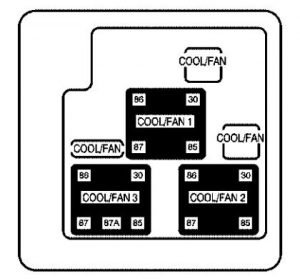
| Fuses | Usage |
| COOL/FAN | Cooling Fan |
| COOL/FAN | Cooling Fan Relay Fuse |
| COOL/FAN | Cooling Fan Fuse |
| Relays | Usage |
| COOL/FAN 1 | Cooling Fan Relay 1 |
| COOL/FAN 3 | Cooling Fan Relay 3 |
| COOL/FAN 2 | Cooling Fan Relay 2 |
WARNING: Terminal and harness assignments for individual connectors will vary depending on vehicle equipment level, model, and market.

