Chevrolet Malibu (1997 – 2003) – fuse box diagram
Year of production: 1997, 1998, 1999, 2000, 2001, 2002, 2003
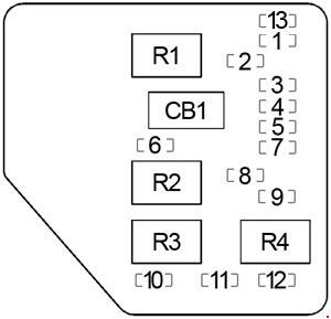
Passenger Compartment Fuse Box (Left)
Chevrolet Malibu – fuse box diagram – passenger compartment (left)
No. A Protected Component
1
25
Wipers, Multifunction Switch
2
10
Trunk Release, Remote Keyless Entry
3
10
Turn Sigals
4
10
Power Mirrors
5
10
Air Bag (Sensing & Diagnostic Module (SDM))
6
10
Body Control Module (BCM)
7
10
Powertrain Control Module (PCM)
8
15
Power Door Lock
9
10
Instrument Panel Cluster, Body Control Module
10
15
Stop Lamps
11
10
Hazard Lamps
12
10
Climate Control, Cluster, Data Link Connector
13
10
Radio
Relay
R1
Trunk Release
R2
Power Door Lock (Unlock)
R3
Power Door Lock (Lock)
R4
Driver Door Unlock
Circuit Breaker
CB1
Power Seat
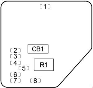
Passenger Compartment Fuse Box (Right)
Chevrolet Malibu – fuse box diagram – passenger compartment (right)
No. A Protected Component
1
10
Interior Lamps (Dimming)
2
2
Cruise Control Switch
3
20
Climate Control
4
10
Cruise Control Module, Brake Switch, Body Control Module (BCM)
5
10
Fog Lamps
6
10
Interior Lamps (Non-Dimming)
7
10
Radio, Clock
8
20
Sunroof
Relay
R1
Fog Lamps
Circuit Breaker
CB1
Power Windows
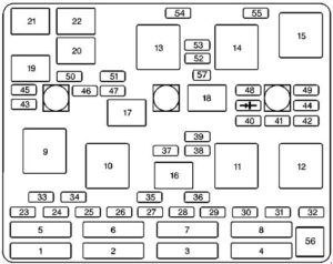
Engine Compartment Fuse Box
Chevrolet Malibu – fuse box diagram – engine compartment
No. A Protected Component
1
30
Ignition Switch
2
30
Passenger Compartment Fuse Box (Right (Fuse: “1”, “5”, “6”))
40
Passenger Compartment Fuse Box (Left (Fuse: “2”, “4”, “8”, “CB1”)
3
30
Passenger Compartment Fuse Box (Left (Fuse: “6”, “10”, “11”, “12”)
4
50
ABS
30
Passenger Compartment Fuse Box (Right (Fuse: “1”, “5”, “6”))
5
40
Ignition Switch
6
30
Air Pump
7
40
Passenger Compartment Fuse Box (Left (Fuse: “2”, “4”, “8”, “CB1”)
40
ABS
8
30
Cooling Fan No.1 (Left)
23
–
–
24
–
–
25
–
–
26
–
–
27
–
–
28
–
–
29
–
–
30
–
–
31
–
–
32
–
–
33
30
Rear Window Defogger
34
20
Cigar Lighter, Accessory Power Outlets
35
10
Generator
10
ABS
36
15
ABS
37
10
Air Conditioning Compressor, Body Control Module (BCM)
38
10
Automatic Transaxle
39
10
Powertrain Control Module (PCM), Ignition
40
10
ABS, ABS Relay
41
10
Ignition Control Module
42
10
Back-Up Lamps, Automatic Transaxle Shift Lock Control System
43
15
Horn
44
10
Powertrain Control Module (PCM), Mass Air Flow (MAF) Sensor
45
15
Parking Lamps
46
10
Climate Control System, Air Temperature Actuator, Daytime Running Lamps Relay, Rear Window Defogger Relay
47
10
Evaporative Emission (EVAP) Canister Purge Valve, Evaporative Emission (EVAP) Canister Vent Solenoid, Powertrain Control Module (PCM), Heated Oxygen Sensors
48
15
Fuel Pump Relay, Fuel Injectors
49
10
Generator
50
15
Right Headlamp
51
15
Left Headlamp, Automatic Lamp Control Relay
52
15
Cooling Fan No.2 (Right)
53
30
Blower Motor Relay
54
–
–
55
15
Cooling Fan No.2 (Right)
56
–
Fuse Puller
57
–
’97-: j Tach Test Point for Diagnostic Testing
Relay
9
Rear Window Defogger
10
–
11
ABS
12
Cooling Fan No.1
13
Blower Motor
14
Cooling Fan No.2
15
Cooling Fan
16
Air Conditioning Compressor
17
–
18
Fuel Pump
19
Automatic Lamp Control
20
Automatic Lamp Control
21
Horn
22
Daytime Running Lamps (DRL)
Circuit Breaker
CB1
Power Windows
WARNING: Terminal and harness assignments for individual connectors will vary depending on vehicle equipment level, model, and market.
