Year of production: 2004, 2005
Instrument Panel Fuse Block (Driver’s Side)
Some fuses are in a fuse block on the driver’s side of the instrument panel.
Chevrolet Monte Carlo – wiring diagram – fuse box – driver side instrument panel
Mini Fuse
Description
PCM/BCM/CLS TR
Powertrain Control Module, Body Control Module, Cluster (Ignition 0)
WSW
Windshield Wipers, Windshield Washer
PCM (CRANK)
Powertrain Control Module (Crank)
CIG/AUX
Accommodated Device (Accessory)
BCM
Body Control Module (Accessory)
SRS
Supplemental Restraint System
ABS/PCM
Anti-Lock Brake System, Powertrain Control Module, Brake Switch, Crank Relay, Canister Vent Solenoid (Run, Crank)
STOP
Brake Lamps, Body Control Module (Run, Crank)
TURN SIGNAL
Turn Signal Flashers
CRUISE
Cruise Control Steering Column Controls
AC/CRUISE
HVAC Temp Door Motors & Module, Cruise Control Module
A/C FAN
HVAC Blower
STR COL
Steering Wheel Lighting
DR LK
Body Control Module, Door Lock Controls
PWR MIR
Power Mirrors
CLSTR/BCM
Cluster, Body Control Module, Data Link Connector (Battery)
LH HTD ST/BCM
Driver’s Heated Seat, Body Control Module, Battery Controlled Loads
Circuit Breaker
Description
RETAINED ACCESSORY PWR BRKR
Power Window, Sunroof Breaker
Relays
Description
RETAINED ACCESSORY PWR RELAY
Retained Accessory Power Relay
HEADLAMP RELAY
Headlamp Relay
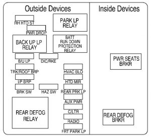
Instrument Panel Fuse Block (Passenger’s Side)
Some fuses are in a fuse block on the passenger’s side of the instrument panel.
Chevrolet Monte Carlo – wiring diagram – fuse box – passenger side instrument panel
Fuse
Description
RH HTD ST
Passenger Heated Seat
PWR DROP
Accommodated Device
B/U LP
Back-Up Lamps
DIC/RKE
Driver Information Center, Remote Keyless Entry, HVAC
TRK/ROOF BRP
Trunk Lamps, Headliner Lamps
HVAC BLO
HVAC Blower Relay
I/P BRP
Instrument Panel Footwell Lamps, Glovebox Lamps
HTD MIR
Heated Mirrors
BRK SW
Brake Switch
HAZ SW
Hazard Switch
REAR PRK LP
Rear Parking Lamps
AUX PWR
Accessory Power Outlet (Battery)
C/LTR
Cigarette Lighter
RADIO
Radio, Radio Amplifier
FRT PARK LP
Front Parking Lamps, Instrumentation Lighting
Relay
Description
PARK LP RELAY
Parking Lamp Relay
BACKUP LP RELAY
Back-up Lamps Relay
BATT RUN DOWN PROTECTION RELAY
Battery Run Down Protection Relay
REAR DEFOG RELAY
Rear Defog Relay, Heated Mirror Relay
Breaker
Description
PWR SEATS BRKR
Power Seat Circuit Breaker
REAR DEFOG BRKR
Rear Defog Breaker
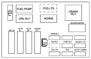
Underhood Fuse Block (Upper)
Some fuses are in a fuse block on the passenger’s side of the engine compartment.
Chevrolet Monte –
Relay
Usage
FUEL PUMP
Fuel Pump
DRL RELAY
Daytime Running Lamps
A.I.R. RELAY
Air Induction Reaction Relay
CRANK RLY
Starter (Crank) Relay
HORNS
Horn
FOG LTS
Fog Lamps
Fuses
Description
LEFT I/P
Left Fuse Block
RT I/P #1
Right Fuse Block (Battery)
RT I/P #2
Right Fuse Block (Battery)
U/HOOD #1
Underhood (Top) Fuse Block
HORN RLY
Horn Relay
BLANK
Blank
BLANK
Blank
FOG RLY
Fog Lamp Relay
F/PMP RLY
Fuel Pump Relay
DRL/EXIT LTS
Low (Left Front) & High (Left Front) Headlamps
EXT LTS
Low (Right Front) & High (Right Front) Headlamps
PCM
PCM Battery
A/C RLY (CMPR)
HVAC Compressor Relay & Generator
BLOWER MOTOR
HVAC Blower Motor
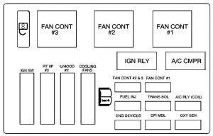
Underhood Fuse Block (Lower)
Some fuses are in a fuse block on the passenger’s side of the engine compartment.
Chevrolet Monte Carlo – wiring diagram – fuse box – underhood fuse block lower
Relay
Usage
FAN CONT #3
Secondary Cooling Fan (Passenger’s Side)
FAN CONT #2
Cooling Fan Control Relay
FAN CONT #1
Primary Cooling Fan (Driver’s Side)
IGN RELAY
Ignition Relay
A/C CMPR
HVAC Compressor
Fuses
Usage
IGN SW
Ignition Switch
RT I/P #3
Rear Defogger, Audio System
U/HOOD #2
Ignition Relay, AIR Pump
COOLING FANS
Cooling fans (Battery)
FAN CONT #2 & #3
Relays #2 & #3
FAN CONT #1
Cooling Fan Control Relays #1
FUEL INJ
Fuel Injectors
TRANS SOL
Transmission Solenoids
A/C RLY (COIL)
HVAC Control Relay
ENG DEVICES
Canister Purge Solenoid, Mass Air Flow Sensor (MAF), AIR Pump Relay & Valve Control
DFI MDL
Direct Fire Ignition Module
OXY SEN
Oxygen Sensors (Pre and Post Converter)
WARNING: Terminal and harness assignments for individual connectors will vary depending on vehicle equipment level, model, and market.

