Citroen Relay (2006 – 2010) – fuse box diagram
Year of production: 2006,2007, 2008, 2009, 2010
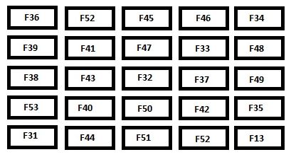
Fuse box in instrument panel (driver side)
Citroen Relay – fuse box diagram – instrument panel
Fuses
Ampere rating [A]
Allocation
12
7,5
Right-hand dipped headlamp
13
7,5
Left-hand dipped headlamp – Headlamp height adjuster
31
7,5
Relay supply
32
10
Minibus interior lighting – Hazard warning lights
33
15
Rear 12 V socket
34
—
Not used
35
7,5
Reversing lights – Water in diesel sensor
36
20
Door locking/unlocking unit
37
10
Brake lights switch – Third brake light – Instrument panel
38
10
Interior relays
39
10
Audio equipment – Diagnostics socket – Alarm siren – Programmable additional heating controls
40
15
De-icing: rear screen (left-hand side), mirror (passenger side)
41
15
De-icing: rear screen (right-hand side), mirror (driver’s side)
42
7,5
ABS control unit and sensor – ESP sensor – Brake lights switch
43
30
Windscreen wiper motor
44
20
Lighter – Front 12 V socket
45
7,5
Electric window and mirror switches (driver’s side) – Passenger electric window
46
—
Not used
47
20
Driver’s electric window motor
48
20
Passenger electric window motor
49
7,5
Rain/brightness sensor – Audio equipment – Driver’s electric window motor – Alarm – Instrument panel controls
50
7,5
Air bags and pre-tensioners unit
51
7,5
Chronotachograph – Cruise control – Air conditioning controls
52
7,5
Passenger compartment relays
53
7,5
Instrument panel – Rear fog lamps
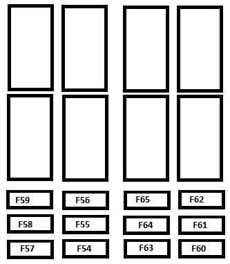
Driver’s pillar fuses
Citroen Relay – fuse box diagram – driver pillar
Fuses
Ampere rating [A]
Allocation
54
—
Not used
55
15
Heated seats
56
15
Rear 12 V socket – Lighter
57
10
Ventilation/heating motor under the driver’s seat
58
10
Direction indicators
59
—
Not used
60
—
Not used
61
—
Not used
62
—
Not used
63
10
Programmable additional heating switch
64
—
Not used
65
30
Rear blower
Fuse box in engine compartment
Fuse
Ampere rating [A]
Allocation
1
10
ABS/ESP pump supply
2
50
Diesel pre-heat unit
3
30
Ignition switch
4
20
Programmable additional heating burner
5
20
Programmable additional heating controls relay
6
40
Fan assembly (high speed)
60
7
40
Fan assembly (low speed)
50
8
40
Air conditioning
9
20
Windscreen wash pump
10
15
Horn
11
15
Diesel pre-heat unit and relay
14
7,5
Right-hand main beam headlamp
15
7,5
Left-hand main beam headlamp
16
7,5
Engine control unit
17
10
Engine control unit
18
7,5
Engine control unit
19
7,5
Air conditioning compressor
20
30
Headlamp wash pump
21
15
Fuel pump supply
22
20
Engine control unit
23
10
ABS/ESP solenoid valves supply
24
—
Not used
30
15
Front fog lamps
WARNING: Terminal and harness assignments for individual connectors will vary depending on vehicle equipment level, model, and market.