
Eagle Summit (1993) – fuse box diagram
Year of production: 1993
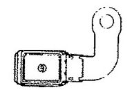
Relay box in engine compartment
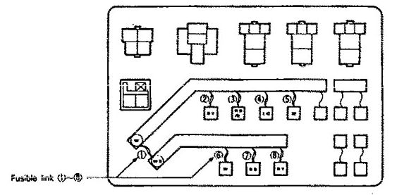
Connected directly to battery positive terminal
| No. | Circuit | Housing color | A |
| 1 | Fusible link No. (6), (7), (8) <when the engine is stopped> and Fusible link No, (2), (3), (4), (5), (6) dedicated fuse No. (2) <after start of the engine> circuit | Black | 80 |
| 2 | MFI circuit | Blue | 20 |
| 3 | Headlight, taillight and generator circuit | Pink | 30 |
| 4 | Radiator fan motor, condenser fan motor and A/C compressor circuit | Pink | 30 |
| 5 | Ignition switch circuit | Green | 40 |
| 6 | Multi-purpose fuse (in the junction block) No. (1), (6), (8), (12), (14) | Green | 40 |
| 7 | Power window circuit | Pink | 30 |
| 8 | Defogger circuit | Blue | 20 |
| 9 | ABS circuit | Yellow | 60 |
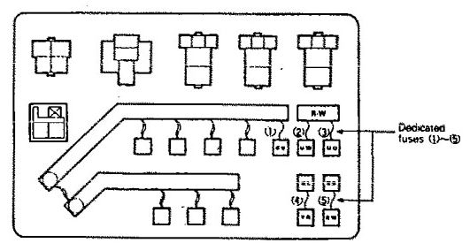
| Power supply circuit | No | A | Housing color | Circuit |
| Battery | 1 | 10 | Red | Hazard light circuit |
| Tailight relay (Battery) | 2 | 10 | Red | Tailight and illumination circuit |
| 3 | — | — | — | |
| Headlight relay (Battery) | 4 | 10 | Red | Upper beam indicator circuit |
| Battery | 5 | 10 | Red | ABS circuit |
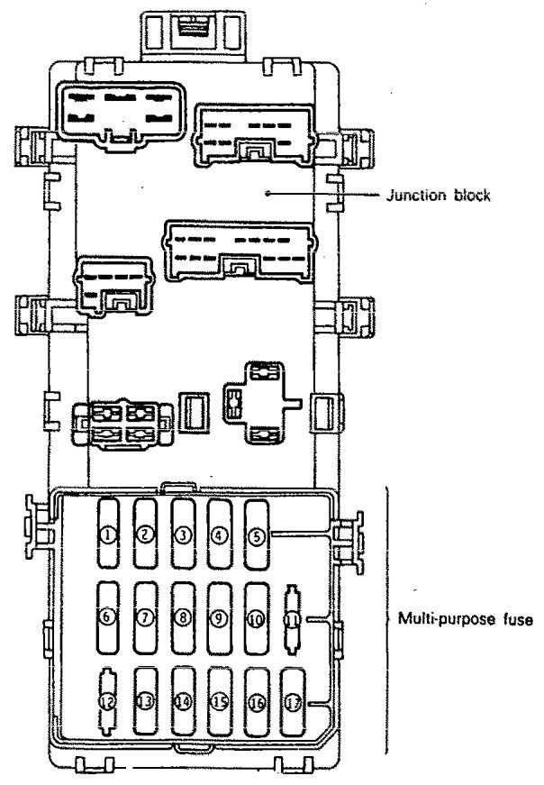
| Power supply circuit | No. | A | Housing color | Load circuit | |
| Battery | 1 | 20 | Yellow | Blower motor | |
| Ignition switch | IG1 | 2 | 10 | Red | Back-up light, buzzer assembly and combination meter <3A/T> |
| 3 | 10 | Red | Combination meter, buzzer assembly and auto-cruise control main switch | ||
| ACC | 4 | 15 | Blue | Cigarette lighter and remote controlled mirror | |
| 5 | 10 | Red | Clock, radio and tape player and auto-cruise control unit | ||
| Battery | 6 | 15 | Blue | Stop light | |
| Ignition switch | IG1 | 7 | 10 | Red | Turn signal and hazard flasher unit |
| Battery | 8 | 15 | Blue | Door lock control relay | |
| Ignition switch | ACC | 9 | 10 | Red | Horn |
| 10 | 15 | Blue | Wiper and washer motor | ||
| — | 11 | — | — | — | |
| Battery | 12 | — | — | — | |
| 13 | — | — | — | ||
| 14 | 10 | Red | Dome light, luggage compartment light, clock, radio and tape player, combination meter, door lock control relay, engine control module, transaxle control module | ||
| Ignition switch | IG2 | 15 | 10 | Red | Blower motor relay, defogger relay, power window relay, automatic compressor control unit, ABS power relay, ABS valve relay and DRL control unit, buzzer assembly, auto-cruise control unit and automatic seat belt control unit |
| 16 | — | — | — | ||
| 17 | 10 | Red | Cobination meter (4A/T> and transaxle control module | ||
WARNING: Terminal and harness assignments for individual connectors will vary depending on vehicle equipment level, model, and market.