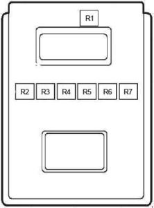
Ford Fiesta (1997 – 2002) – fuse box diagram
Year of production: 1997, 1998, 1999, 2000, 2001, 2002
Passenger Compartment Fuse Box
Type 1
LHD

RHD

Type 2
LHD
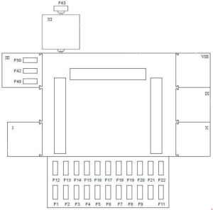
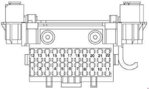
| Number | A | Description |
| 1 | 15 | Cigar lighter |
| 2 | 20 | 1) Clock, Heating, Interior Lights, Clock, Radio Memory |
| 7,5 | 2) Interior Lights, Climate Control Module, Clock, Instrument Panel | |
| 3 | 10 | 2) GEM Module 2) Fridge Van; up to 1999: Refrigeration System Relay, Evaporator Control Relay |
| 4 | 15 | 1) Heated Rear Window, Heated Exterior Mirrors |
| 20 | 2) Heated Rear Window | |
| 5 | 20 | 1) Horn, Alarm |
| 15 | 2) Multifunction Switch (Horn) | |
| 6 | 10 | 1) Left Side Lamp |
| 7,5 | 2) Left Side Lamp, Headlight Range Control, License Plate Light, Climate Control Module, Radio, Heated Rear Window Switch, Instrument Panel, Rear Fog Light Switch, Front Fog Light Switch, Heated Windshield Switch | |
| 7 | 10 | 1) Right Side Lamp |
| 7,5 | 2) Right Side Lamp, License Plate Light | |
| 8 | 15 | Up to 09.1999: Central Locking, Electric Mirrors As of 09.1999: GEM Module |
| 9 | 15 | 1) Seat Height Adjustment |
| 25 | 2) Multifunction Switch (Exterior Light) | |
| 10 | 15 | Heated Front Seat |
| 11 | 30 | Electric Windows, Central Locking |
| 12 | 20 | Wiper Motor, Screen Washer Pump |
| 13 | 15 | 1) Brake Light, Instrument Panel |
| 15 | 2) Brake Light Switch, Climate Control Module, Gearbox Switch (Manual Transmission), Gearbox Position Sensor (Automatic Transmission), Heater Control Valve Solenoid, Heated Rear Window Switch, Instrument Panel | |
| 14 | 10 | Air Bag |
| 15 | 10 | 1) Heated Mirrors |
| 7,5 | 2) Electric Mirrors | |
| 16 | 30 | Heater Blower Motor |
| 17 | 15 | Direction Indicators |
| 18 | 15 | 1) Ignition |
| 15 | 2) GEM Module, Auxiliary Relay, Main Relay, Ignition coil DIS (1,3 L Endura–E, 1,25 and 1,4 L ZETEC–SE), Passive Anti-Theft Module (1,8 L Diesel Endura–DE) | |
| 19 | 10 | 1) Engine Management, Radio, Alarm |
| 7,5 | 2) Fuse No.30, Radio, Clock, Instrument Panel | |
| 20 | 30 | 1) Headlight Washer |
| 10 | 1) RHD: Dim/Dip | |
| 20 | 2) Multifunction Switch (Daytime Running Lights, Exterior Light) | |
| 21 | 15 | 2) As of 09.1999: Central Locking |
| 22 | 10 | Data Link Connector (DLC), Radio |
| 42 | 15 | 2) Up to 09.1999: GEM Module |
| 10 | 2) Fridge Van; as of 09.1999: Refrigeration System Relay, Evaporator Control Relay | |
| 43 | 10 | 2) Daytime Running Light Relay (Parking Lights) |
| 49 | 20 | 2) Daytime Running Lights, Exterior Light |
| 50 | 25 | 2) Exterior Light |
| Relay | ||
| I | Ignition Relay | |
| II | Heated Windshield Relay | |
| III | — | |
| IV | — | |
| V | — | |
| VI | — | |
| VII | Daytime Running Light Relay (Parking Lights) | |
| VIII | Daytime Running Light Relay (DTRL) | |
| IX | Heated Windshield Relay | |
| X | Heated Rear Window Relay | |
| XI | Daytime Running Light Relay (Parking Lights) | |
| 1) Haynes 2) Electrical Wiring Diagrams (CG1647es) |
||
Engine Compartment Fuse Box
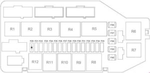
| Number | A | Description |
| 20 | — | Diode |
| 21 | — | — |
| 22 | — | — |
| 23 | 10 | Left Main Beam |
| 24 | 10 | Right Main Beam |
| 25 | 10 | Left Low Beam |
| 26 | 10 | Right Low Beam |
| 27 | 10 | Petrol Engines: Lambda Sensor |
| 15 | Diesel Engines: Fuel Heater | |
| 28 | 15 | 1,8 L Diesel Endura–DE: PCM Module, EGR, Glow Plug Relay, Engine Cooling Fan Relay, High Speed Cooling Fan Relay (with air conditioning), Air Conditioning Relay, Vehicle Speed Sensor (VSS) Petrol Engines: Fuel Pump Relay, Engine Cooling Fan Relay, High Speed Cooling Fan Relay (with air conditioning), Air Conditioning Relay, Vehicle Speed Sensor (VSS), Passive Anti-Theft Module (1,25 L ZETEC–SE 1,3 L Endura–DE), PCM Module, Mass Air Flow Sensor (MAF; 1,4 L ZETEC–SE), Idle Air Control Valve, Injector, Canister Purge Valve |
| 29 | 20 | Air Conditioning Relay, Front Fog Light Relay, Dual Pressure Switch, Refrigeration System Relay (Fridge Van), Evaporator Control Relay (Fridge Van) |
| 30 | 3 | ABS |
| 31 | 30 | ABS |
| 32 | 3 | PCM Module |
| 33 | 30 | ABS (all models with ABS), Engine Cooling Fan (without ABS, without A/C) |
| 34 | 30 | PCM Module |
| 35 | 10 | Passive Anti-Theft Module (1,8 L Diesel Endura–DE), Fuel Pump Relay |
| 36 | 60 | Engine Cooling Fan Relay, High Speed Cooling Fan Relay (with air conditioning), Glow Plug Relay, Inhibitor Relay |
| 37 | 40 | Heated Windshield Relay |
| 60 | Fridge Van: Cooling Fan Relay (Refrigeration System), High Speed Cooling Fan Relay | |
| 38 | 10 | Main Relay |
| 39 | 60 | Daytime Running Light Relay (DTRL), Fuse No.: 1, 2, 3, 4, 5, 21, 22 (Passenger Compartment Fuse Box) |
| 40 | 60 | Ignition Lock, Fuse No.: 42, 50 (Passenger Compartment Fuse Box) |
| Relay | ||
| R1 | Auxiliary Relay | |
| R2 | Inhibitor Relay | |
| R3 | Diesel Engines: Glow Plug Relay | |
| R4 | Engine Cooling Fan Relay | |
| R5 | High Speed Cooling Fan Relay | |
| R6 | Air Conditioning Relay | |
| R7 | Air Conditioning Relay | |
| R8 | Main Relay | |
| R9 | Petrol Engines: Fuel Pump Relay Diesel Engines: Fuel Heater Relay |
|
| R10 | Front Fog Light Relay | |
| R11 | Low Beam Relay | |
| R12 | High Beam Relay | |
| Number | Description |
| R1 | Refrigeration System |
| R2 | Evaporator |
| R3 | Chiller |
| R4 | Cooling Fan |
| R5 | High Speed Cooling Fan |
| R6 | Low Speed Cooling Fan |
| R7 | Clutch Control |
WARNING: Terminal and harness assignments for individual connectors will vary depending on vehicle equipment level, model, and market.

