Ford Mustang (2014 – 2015) – fuse box diagram
Year of production: 2014, 2015
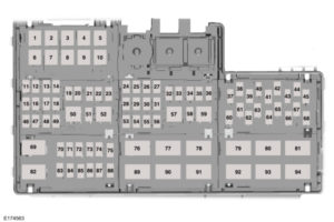
Power distribution box

| Fuse or relay | Ampere rating [A] | Protected components |
| 1 | — | Not used |
| 2 | — | Not used |
| 3 | — | Not used |
| 4 | — | Not used |
| 5 | 50* | Automatic brake system pump |
| 6 | 50* | Body control module |
| 7 | 60* | Body control module |
| 8 | 50* | Body control module |
| 9 | 40* | Rear window defroster |
| 10 | 40* | Blower motor |
| 11 | 30** | Left-hand front window |
| 12 | 30** | Driver seat |
| 13 | 30** | Passenger seat |
| 14 | 30** | Climate-controlled seat module |
| 15 | 20** | Convertible top motor |
| 16 | — | Not used |
| 17 | 20** | Convertible top motor |
| 18 | — | Not used |
| 19 | 20*** | Steering column lock relay |
| 20 | 10*** | Brake on-off switch |
| 21 | 20*** | Horn |
| 22 | 10*** | Powertrain control module relay |
| 23 | 10*** | Air conditioning clutch |
| 24 | 30*** | Voltage quality module |
| 25 | — | Not used |
| 26 | 25** | Windshield wiper motor |
| 27 | — | Not used |
| 28 | 30** | Automatic brake system valve |
| 29 | 30** | Electronic fan 1 |
| 30 | 30** | Starter motor solenoid |
| 31 | 40** | Electronic fan 3 |
| 32 | 10*** | Latch relay coil |
| 33 | 20*** | Left-hand high-intensity discharge headlamps |
| 34 | — | Not used |
| 34 | 20*** | Right-hand high-intensity discharge headlamps |
| 36 | 10*** | Alt sense |
| 37 | — | Not used |
| 38 | 20*** | Vehicle power 1 |
| 39 | — | Not used |
| 40 | 20*** | Vehicle power 2 |
| 41 | 15*** | Fuel injectors |
| 42 | 15*** | Vehicle power 3 |
| 43 | — | Not used |
| 44 | 15*** | Vehicle power 4 |
| 45 | — | Not used |
| 46 | — | Not used |
| 47 | — | Not used |
| 48 | — | Not used |
| 49 | 30** | Fuel pump |
| 50 | — | Steering column lock relay |
| 51 | — | Not used |
| 52 | — | Horn relay |
| 53 | 20** | Cigar lighter |
| 54 | 20** | Auxiliary power point |
| 55 | 25** | Electronic fan 2 |
| 56 | — | Not used |
| 57 | — | Air conditioning clutch relay |
| 58 | — | Not used |
| 59 | — | Not used |
| 60 | 5*** | Powertrain control module |
| 61 | — | Not used |
| 62 | 5*** | Anti-lock brakes run-start switch |
| 63 | — | Not used |
| 64 | 5*** | Electronic power assist steering |
| 65 | — | Not used |
| 66 | 5*** | Blind spot information system. Rear view camera. Air conditioning compressor relay coils |
| 67 | — | Not used |
| 68 | 10*** | Headlamp leveling switch |
| 69 | — | Auxiliary power point relay |
| 70 | 10*** | Heated exterior mirrors |
| 71 | — | Not used |
| 72 | 5*** | Rain sensor module |
| 73 | — | Not used |
| 74 | 5*** | Mass air flow sensor |
| 75 | — | Not used |
| 76 | — | Rear window defroster |
| 77 | — | Electronic cooling fan 2 |
| 78 | — | Left-hand high-intensity discharge headlamp relay (export) |
| 79 | — | Right-hand high-intensity-discharge headlamp relay (export) |
| 80 | — | Windshield wiper relay |
| 81 | — | Starter motor solenoid |
| 82 | — | Powertrain control module relay |
| 83 | — | Not used |
| 84 | — | Not used |
| 85 | — | Not used |
| 86 | — | Not used |
| 87 | — | Not used |
| 88 | — | Not used |
| 89 | — | Electronic fan 1 relay |
| 90 | — | Not used |
| 91 | — | Electronic fan 3 relay |
| 92 | — | Blower motor relay |
| 93 | — | Not used |
| 94 | — | Fuel pump relay |
|
*J-case fuses
**M-case fuses
***Micro fuses
|
||
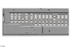
Passenger compartment fuse panel

The fuse panel is in the right-hand side of the passenger footwell behind a trim panel and plastic key code card.
| Fuse or relay number | Ampere rating [A] | Protected components |
| 1 | 10 | Demand lamps |
| 2 | 7,5 | Power mirror memory module |
| 3 | 20 | Driver console unlock |
| 4 | 5 | Not used (spare) |
| 5 | 20 | Subwoofer amplifier |
| 6 | 10 | Not used (spare) |
| 7 | 10 | Not used (spare) |
| 8 | 10 | Not used (spare) |
| 9 | 10 | Not used (spare) |
| 10 | 5 | Not used (spare) |
| 11 | 5 | Not used (spare) |
| 12 | 7,5 | Climate control module |
| 13 | 7,5 | Gateway module. Steering column control module. Instrument cluster |
| 14 | 10 | Not used (spare) |
| 15 | 10 | Gateway module |
| 16 | 15 | Decklid release |
| 17 | 5 | Not used (spare) |
| 18 | 5 | Intrusion sensor module |
| 19 | 7,5 | Passenger airbag deactivation indicator |
| 20 | 7,5 | Not used (spare) |
| 21 | 5 | In-vehicle temperature and humidity sensor |
| 22 | 5 | Occupant classification system module |
| 23 | 10 | Switches. Power windows. Rear-view mirror |
| 24 | 20 | Central lock unlock |
| 25 | 30 | Not used (spare) |
| 26 | 30 | Right-hand front-window motor |
| 27 | 30 | Amplifier |
| 28 | 20 | Auxiliary body module |
| 29 | 30 | Left-hand rear-window power |
| 30 | 30 | Right-hand rear-window power |
| 31 | 15 | Not used (spare) |
| 32 | 10 | Remote keyless entry. Multi-function display. SYNC. Global positioning system module. Gauges |
| 33 | 20 | Audio head unit |
| 34 | 30 | Run-start bus35 |
| 35 | 5 | Restraints control module |
| 36 | 15 | Auxiliary body module |
| 37 | 15 | Power distribution box run-start bus |
| — | 30 | Not used (spare) |
WARNING: Terminal and harness assignments for individual connectors will vary depending on vehicle equipment level, model, and market.


