Ford Windstar (2003) – fuse box diagram
Year of production: 2003
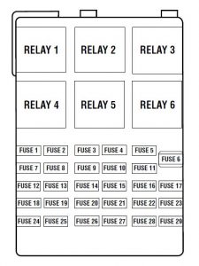
Passenger compartment fuse panel
The fuse panel is located below and to the left of the steering wheel by the brake pedal.

| Fuse | Ampere rating [A] | Circuit protected |
| 1 | 10 | Stepwell lamps, Puddle lamps, 2nd row reading lamps, 3rd row reading lamps, Cargo lamp, Dome lamp, Map lamp, Visor/Vanity lamps, Remote Keyless Entry (RKE) keypad, Turn signal mirrors |
| 2 | 25 | I/P Courtesy Lamps, Video Cassette Player (VCP) |
| 3 | 15 | Power mirror motors, Adjustable pedal motor, Memory module (if equipped) |
| 4 | — | Not Used |
| 5 | 20 | Console Power Point |
| 6 | 15 | Radio, Compact Disc (CD) changer, RKE module, Power Sliding Door (PSD) module, Rear seat radio controller (if equipped), Rear seat entertainment module (if equipped) |
| 7 | 15 | Left rear turn lamp, Backup lamps, Right stop lamp, Right rear park lamp, License Lamps |
| 8 | 20 | Rear electronic module (RHF/RH sliding/LH sliding/Liftgate door lock motors, Aux. air blend door motor, Aux. air mode door motor) |
| 9 | 10 | Cluster, Powertrain Control Module (PCM) relay (coil) |
| 10 | 15 | Heated backlite relay (coil), Speed control module, Anti-lock Brake System (ABS) module or IVD Module, Heated seat switch (if equipped), Heated seat module (if equipped), Cluster, Front temp blend door actuator, Brake shift interlock solenoid, PCM, PSD module, Reverse Sensing System (RSS), Front A/C control head, Steering wheel angle sensor (if equipped) |
| 11 | 15 | Electric brake controller, Brake shift interlock solenoid, Rear electronic module |
| 12 | 20 | Center high-mounted stop lamp |
| 13 | 10 | Right rear turn lamp, Left stop lamp, Left rear park lamp |
| 14 | 10 | Autolamp sensor, Transmission overdrive cancel switch, Front electronic module, Compass module, Electrochromatic mirror, PSD overhead console switch |
| 15 | 20 | Console power point |
| 16 | 10 | Cluster |
| 17 | 20 | Cigar Lighter/Powerpoint, Datalink Connector |
| 18 | 15 | Quarter Window Motors, RH window switch backlighting, RH lock switch backlighting, Master control switch (LH) backlighting, Radio, VCP, Liquid Crystal Display (LCD), Front electronic module |
| 19 | 10 | Starter interrupt relay (coil) |
| 20 | — | Not Used |
| 21 | — | Not Used |
| 22 | 10 | Heated Mirrors |
| 23 | 20 | Body power point, Auxiliary blower relay #1 and #2 coils |
| 24 | — | Not Used |
| 25 | 10 | Radio (Anti-theft) |
| 26 | 10 | Air bag module, Passenger air bag deactivated indicator, Passenger seat weight pressure sensor ECU |
| 27 | 15 | Not Used |
| 28 | 10 | Cluster |
| 29 | 2 | Speed control deactivation switch |
| Relay 1 | — | Switched System Power Relay #4 |
| Relay 2 | — | Accessory Delay Relay |
| Relay 3 | — | Front Blower Motor Relay |
| Relay 4 | — | Switched System Power Relay #3 |
| Relay 5 | — | Rear Defrost Relay |
| Relay 6 | — | Auxiliary Blower Motor Relay |
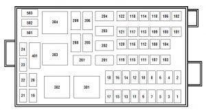
Power distribution box
The power distribution box is located in the engine compartment.

| Fuse | Ampere rating [A] | Circuit protected |
| 1 | 30* | Powertrain Control Module (PCM) relay |
| 2 | 10* | PCM, Front electronic module (FEM) |
| 3 | 10* | A/C Compressor Clutch |
| 4 | 25* | Horns, Horn Relay (coil) |
| 5 | 15* | Fuel pump motor, PCM |
| 6 | 30* | Front wiper motor, Front wiper relay, Front washer pump, FEM |
| 7 | 25* | Rear wiper motor, Rear washer pump, Rear wiper relay (coil) |
| 8 | — | Not Used |
| 9 | 15* | Right headlamp |
| 10 | 15* | Right front park lamp, Right front turn lamp, Right front cornering lamp, Right front auxiliary driving lamp |
| 11 | 15* | Left front park lamp, Left front turn lamp, Left front cornering lamp, Left front auxiliary driving lamp |
| 12 | 15* | Left headlamp (low and high beam) |
| 13 | 10 | Alternator field sense |
| 14 | 10* | FEM (left door lock motor) |
| 15 | 20* | Trailer tow park lamps |
| 16 | 20- | Trailer tow turn lamps |
| 17 | Not used | |
| 18 | — | Not used |
| 19 | 15* | AX4S transaxle, Vapor Management Valve (VMV), A/C clutch relay coil, EGR control solenoid, Engine fuel control HO2S #11 sensor, Engine fuel control HO2S #21 sensor, Catalyst monitor HO2S #12 sensor, Catalyst monitor HO2S #22 Sensor, Canister vent solenoid, Intake manifold runner control |
| 20 | 15* | Ignition coil, Intake Air Control (IAC) valve, Fuel injectors, Mass Air Flow (MAF) sensor, Fuel pump relay coil, Intake manifold runner control, High-speed cooling fan relay coil, Low-speed cooling fan relay coil, PCM, Passive anti-theft receiver |
| 21 | — | Not Used |
| 22 | — | Not Used |
| 23 | — | Not Used |
| 24 | — | Not Used |
| 101 | 40** | Anti-lock Brake System (ABS) module or IVD Module |
| 102 | 40** | ABS Module or IVD Module |
| 103 | 40** | SSP4 Relay, SSP4 Relay (coil) |
| 104 | 40** | Anti-lock Brake System (ABS) module or IVD Module |
| 105 | 30** | Starter motor solenoid, Ignition switch |
| 106 | 30** | Delayed accessory relay, Delayed accessory relay coil, FEM- right-hand front window motor |
| 107 | 50** | Delayed accessory relay, Delayed accessory relay coil, FEM- right-hand front window motor |
| 108 | — | Not Used |
| 109 | 30** | Heated seat modules |
| 110 | 50** | Right-hand Power Sliding Door (PSD) module |
| 111 | 40** | Fuse Junction Box |
| 112 | 30** | Trailer tow, Electric brake controller |
| 113 | 30** | FEM – left-hand window motor |
| 114 | 40** | SSP3 relay, SSP3 relay coil |
| 115 | 50** | Fuse junction box bus #2 |
| 116 | 30** | Heated backlight relay |
| 117 | 40** | Auxiliary blower relay coil, Auxiliary blower motor |
| 118 | 50** | Left-hand PSD module |
| 119 | 30** | Fuse junction box bus #1 |
| 120 | 40** | Front blower relay coil, Front blower motor |
| 121 | 20** | Ignition switch, Rear defrost relay coil |
| 122 | 40** | Right-hand power seat motors, Right-hand power lumbar motor |
| 201 | — | Not Used |
| 202 | — | Front Wiper ON/OFF Relay |
| 203 | — | Rear Wiper Relay |
| 204 | — | A/C Clutch Relay |
| 205 | — | Horn Relay |
| 206 | — | Not Used |
| 207 | — | Fuel Pump Relay |
| 208 | — | Not Used |
| 209 | — | Front Wiper HI/LO Relay |
| 301 | — | Starter interrupt relay |
| 302 | — | High-speed engine cooling fan relay |
| 303 | — | Low-speed engine cooling fan relay |
| 304 | — | PCM Relay |
| 401 | — | Not Used |
| 501 | — | PCM diode |
| 502 | — | Not Used |
| 503 | — | Not Used |
| * Mini Fuses** Maxi Fuses | ||
WARNING: Terminal and harness assignments for individual connectors will vary depending on vehicle equipment level, model, and market.


