Honda Accord (2005) – fuse box diagram
Year of production: 2005
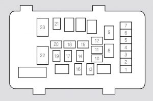
Fuse block (Engine compartment)

| Number | Ampere rating [A] | Circuits Protected |
| 1 | 10 | Left Headlight Low Beam |
| 2 | (30) | (Rear Defroster Coil) |
| 3 | 10 | Left Headlight High Beam |
| 4 | 15 | Small Light |
| 5 | 10 | Right Headlight High Beam |
| 6 | 10 | Right Headlight Low Beam |
| 7 | 7,5 | Back Up |
| 8 | 15 | FI ECU |
| 9 | 20 | Condenser fan |
| 10 | — | Not Used |
| 11 | 20 | Cooling Fan |
| 30* | Cooling Fan | |
| 12 | 7,5 | MG. Clutch |
| 13 | 20 | Horn, Stop |
| 14 | 40 | Rear Defroster |
| 15 | 40 | Back Up, ACC |
| 16 | 15 | Hazard |
| 17 | 30 | ABS Motor |
| 30* | TCS Motor | |
| 18 | 20 | ABS F/S |
| 40* | TCS | |
| 19 | 40 | Option |
| 20 | (40) | Option |
| 21 | 40 | Heater Motor |
| 22 | 100 | Battery |
| — | Not Used | |
| 23 | 50 | +B IGI Main |
| 50 | Power Window Main | |
| * 6-cylinder models | ||
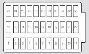
Interior fuse panel

| Description | Ampere rating [A] | Circuits Protected |
| 1*1 | (15) | DBW |
| 2 | 15 | Ignition Coil |
| 3*2 | (10) | Daytime Running Light* |
| 4 | 15 | Laf Heater |
| 5 | 10 | Radio |
| 6 | 7,5 | Interior Light |
| 7 | 10 | Back-Up Lights |
| 8 | 20 | Door Lock |
| 9 | 15 | Front Accessory Sockets |
| 10 | 7,5 | IG OPDS (Occupant Position Detection System) |
| 11 | 30 | IG Wiper |
| 12 | — | Not Used |
| 13 | — | Not Used |
| 14 | (20) | Driver’s Power Seat Slide |
| 15 | (20) | Heated Seat |
| 16 | (20) | Driver’s Power Seat Recline |
| 17 | — | Not Used |
| 18 | 15 | IG ACG |
| 19 | 15 | IG Fuel Pump |
| 20 | 7,5 | IG Washer |
| 21 | 7,5 | IG Meter |
| 22 | 10 | IG SRS |
| 23 | 7,5 | IGP (PGM-FI ECU) |
| 24 | — | Not Used |
| 25 | — | Not Used |
| 26 | 20 | Passenger’s Power Window |
| 27 | 20 | Driver’s Power Window |
| 28 | (20) | Moonroof |
| 29 | — | Not Used |
| 30 | 7,5 | IG HAC |
| 31 | — | Not Used |
| 32 | 7,5 | ACC |
| 33 | — | Driver’s Power Window |
| * – On Canadian models | ||
WARNING: Terminal and harness assignments for individual connectors will vary depending on vehicle equipment level, model, and market.


