KIA K900 (2012 – 2014) – fuse box diagram
Year of production: 2012, 2013, 2014
Instrument panel fuse panel
Inside the fuse/relay panel covers, you can find the fuse/relay label describing fuse/relay name and capacity.
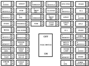
| Fuse name | Fuse rating [A] | Circuit protected |
| AUDIO 2 | 10 | A/V & Navigation Head Unit, TMU |
| MODULE 3 | 10 | A/C Control Module, Electro Chromic Mirror, Rear Seat Console Switch, Driver Haptic Control Module, Rear CCS Control Module LH/RH, Driver/Passenger IMS Control Module, Driver Power Seat Module, Rear Seat Warmer Control Module LH/RH, Rear Smart Junction Box (IPS Control Module) |
| MODULE 2 | 10 | Steering Tilt & Telescopic Module, LDWS Camera Module, Crash Pad Switch, Stop Lamp Switch, A/T Console Switch, Electric Parking Brake Switch, Console Switch, Smart Cruse Control Radar, Air Sus, TPMS, PAS |
| SPARE | 10 | Spare |
| WIPER | 10 | Auto Light & Rain Sensor |
| MODULE 1 | 10 | BCM, Trunk Lid Main Switch, Low Panel Switch |
| MEMORY 2 | 10 | External Buzzer, Driver Smart Connector, Passenger Smart Connector |
| DRV HEAT | 15 | Driver Haptic Control Module, Driver CCS Module |
| PASS HEAT | 15 | Passenger CCS Module |
| WINDOW LH | 30 | Rear Power Window Module LH, Rear Power Window Module LH |
| HEADREST | 15 | Active Headrest Sensor |
| BCM | 10 | BCM, Multifunction Switch, Driver/Passenger Power Seat Switch, Rear Door Module LH/RH |
| EPB 2 | 15 | Electric Parking Brake Module |
| P/HANDLE | 15 | Steering Tilt & Telescopic Module |
| B/ALARM | 10 | BCM |
| INHIBITOR 1 | 10 | W/O Electric ATM Shift Lever : Sport Mode Switch With Electric ATM Shift Lever : Electric ATM Shift Lever |
| P/DOOR DRV | 15 | Driver Door Latch |
| PASS P/SEAT | 20 | W/O IMS : Passenger Seat Relay Box With IMS : Passenger IMS Control Module |
| P/DOOR RR LH | 15 | Rear Door Latch LH |
| DRV P/SEAT | 30 | Driver Lumbar Support Valve, Driver Lumbar Support Switch, Driver Power Seat Module |
| S/ROOF 2 | 10 | Sunroof Motor |
| SMART KEY 2 | 10 | Metal Core Block (PCB #2) (P/N Relay), Smart Key Control Module |
| S/ROOF 1 | 20 | Sunroof Motor |
| START | 10 | Start/Stop Button Switch |
| MODULE 5 | 10 | Surround View Unit, Parking Guide Unit, Head-UP, Instrument Cluster, Driver Lumbar Support Valve, Rear Seat Console Switch, Rear Seat Warmer Control Module LH/RH, Rear Massage Control Module LH/RH, Rear Smart Junction Box (IPS Control Module) |
| CLUSTER | 10 | Instrument Cluster, Head-Up Display |
| SMART KEY 1 | 25 | Smart Key Control Module |
| DOOR LAMP | 10 | Driver Door Module, Passenger Door Module |
| STR’G HTD | 15 | Clock Spring |
| MODULE 6 | 10 | Smart Key Control Module, BCM |
| A/BAG | 15 | Driver Seat Belt Pretensioner, Passenger Seat Belt Pretensioner, SRS Control Module |
| A/BAG IND | 10 | Instrument Cluster |
| IGN 1 | 20 | E/R Fuse & Relay Box LH (FUSE : F20, F21, F23, F25, F26, F27) |
| MEMORY 1 | 10 | Passenger IMS Control Module, Driver/Passenger Door Module, Driver/Passenger Power Seat Switch, Rear Door Module LH/RH, Power Trunk Module, Instrument Cluster, BCM, Security Sensor, Analogue Clock, A/C Control Module, Head-Up Display |
| MULTI MEDIA | 10 | Keyboard, A/V Navigation Head Unit, Front Monitor, TMU |
| ROOM LAMP | 10 | Rear Seat Foot Lamp LH/RH, Trunk Room Lamp LH/RH, Driver/Passenger Foot Lamp, Room Lamp, Overhead Console Lamp, Front Vanity Lamp Switch LH/RH, Rear Vanity Lamp Switch LH/RH, Garnish Lamp LH/RH, Garnish Center Lamp, Glove Box Lamp |
| MEMORY 3 | 10 | RF Receiver |
| EPB 1 | 15 | Electric Parking Brake Module |
| SPARE | 15 | Spare |
| IGN 2 | 20 | E/R Fuse & Relay Box LH (Fuse : F29, F30) |
| A/CON 1 | 10 | A/C Control Module, Ionizer, Metal Core Block (PCB #2) (Blower Relay) |
| AFLS | 15 | Adaptive Front Lighting Module, HEAD LAMP LH/RH |
| SPARE | 10 | Spare |
| P/OUTLET FR | 20 | Front Cigarette Lighter |
| MODULE 4 | 10 | Electric ATM Shift Lever, Analogue Clock, BCM, Surround View Unit, Overhead Console Lamp, Parking Guide Unit |
| AUDIO 1 | 10 | A/V & Navigation Head Unit, Front/Rear Monitor Module, Keyboard, Smart Key Control Module, Rear Seat Audio Switch, AMP, TMU |
| SPARE | 10 | Spare |
| P/OUTLET RR | 20 | P/OUTLET RR, Front Power Outlet |
Engine compartment fuse panel (Driver’s side)
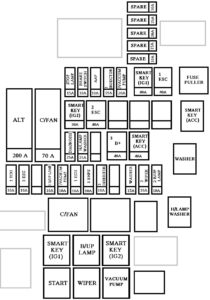
| Fuse name | Fuse rating [A] | Circuit protected |
| Stop Lamp | 15 | Stop Signal Electronic Module |
| Brake SW | 10 | Stop Lamp Switch, Smart Key Control Module |
| AAF | 10 | Not Used |
| Injector 1 | 15 | Injector Drive Box |
| SMK (IGN1) | 40 | E/R Fuse & Relay Box LH (RLY.5) |
| ESC 1 | 40 | ESC Control Module |
| ALT | 200 | E/R Fuse & Relay Box LH (Fuse : F9, F15, F16, F18, F19), Alternator |
| Cooling | 70 | E/R Fuse & Relay Box LH (RLY.6) |
| SMK (IGN2) | 30 | E/R Fuse & Relay Box LH (RLY.3) |
| ESC 2 | 40 | ESC Control Module |
| Diagnosis | 25 | Multipurpose Check Connector |
| H/Lamp Washer | 25 | Not Used |
| Battery 3 | 40 | Smart Junction Box (Fuse : F5, F6, F8, F9, F10) |
| SMK (ACC) | 40 | E/R Fuse & Relay Box LH (RLY.9) |
| TCU 1 | 10 | ECM, Transmission Range Switch, Transmission Park Postilion Sensor & Switch |
| ESC 3 | 10 | Steering Angle Sensor, ESC Control Module |
| B/UP Lamp 1 | 10 | E/R Fuse & Relay Box LH (RLY.4) |
| Vaccum Pump 1 | 10 | E/R Fuse & Relay Box LH (RLY.10), Vaccum Pump Switch |
| ECU 1 | 10 | ECU |
| EHPS 1 | 10 | EHPS Module |
| Inhibitor 2 | 10 | A/T Console Switch, Electric ATM Shift Lever |
| Washer | 15 | E/R Fuse & Relay Box LH (RLY.8) |
| Wiper 2 | 10 | E/R Fuse & Relay Box LH (RLY.1) |
| B/UP Lamp 2 | 10 | Back View Camera & Back-Up Lamp, A/T Console Switch, Electro Chromic Mirror, A/V & Navigation Head Unit |
| Vaccum Pump 2 | 20 | E/R Fuse & Relay Box LH (RLY.10) |
Engine compartment fuse panel (Passenger’s side)
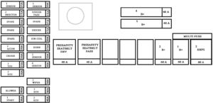
| Fuse | Fuse name | Fuse rating [A] | Circuit protected |
| METAL CORE BLOCK (PCB #1) |
Sensor 3 | 10 | Rear Smart Junction Box (Fuel Pump Relay) |
| P/Door PASS | 15 | Passenger Door Latch | |
| SPARE | 15 | Spare | |
| Deicer | 15 | Metal Core Block (PCB #1) (Front Deicer Relay), Ignition Coil #1~8 | |
| Ignition Coil | 20 | Ignition Coil #1~6, Condenser #1, #2 | |
| Horn | 15 | Metal Core Block (PCB #1) (Horn Relay) | |
| Sensor 2 | 10 | Mass Air Flow Sensor, Oxygen Sensor #1~4, E/R Fuse & Relay Box LH (RLY.6) | |
| Sensor 4 | 15 | CMP Sensor #1~4 | |
| Wiper 3 | 30 | Wiper Motor | |
| ECU 3 | 30 | Metal Core Block (PCB #1) (ECU Main Relay) | |
| ECS 2 | 40 | Metal Core Block (PCB #1) (Air ECS Relay) | |
| METAL CORE BLOCK (PCB #2) |
Sensor 1 | 15 | Purge Control Solenoid Valve, ECM, Variable Intake Solenoid Valve, Oil Control Valve #1~4 |
| Injector 2 | 15 | Injector #1~6, Injector #1~8 | |
| SPARE | 10 | Spare | |
| SPARE | 20 | Spare | |
| SPARE | 10 | Spare | |
| A/CON 2 | 10 | A/C Control Module | |
| Cruise | 10 | Smart Cruise Control Radar | |
| TCU 2 | 15 | TCM | |
| ECU 2 | 10 | ECM | |
| Blower | 40 | Metal Core Block(PCB) (Blower Relay) | |
| Start 1 | 30 | E/R Fuse Relay Box LH (RLY.2) | |
| MULTI FUSE |
Presafety Seat Belt DRV |
40 | Driver Seat Belt Pretensioner |
| Presafety Seat Belt PASS |
40 | Passenger Seat Belt Pretensioner | |
| Battery 2 | 60 | Smart Junction Box (Fuse : F13~20, F23, F24, F27, F28, IPS5~8, Arisu-LT2) | |
| Battery 1 | 60 | Smart Junction Box (Fuse : F38, IPS1, 3, Arisu-LT1, Leak Current Autocut Device) | |
| EHPS 2 | 80 | EHPS Module | |
| FUSE | Battery 4 | 60 | Metal Core Block (PCB #1) (Fuse : F2, F4, F6, F10, F11, F12) |
| Battery 5 | 60 | Metal Core Block (PCB #2) (Fuse : F7, F11) |
Trunk fuse panel
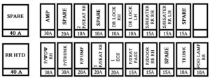
| Fuse name | Fuse rating [A] | Circuit protected |
| Rear HTD | 40 | Rear Defogger Relay |
| P/WDW RH | 30 | Passenger Power Window Module, Rear Power Window Module RH |
| P/Trunk | 30 | Power Trunk Module |
| F/Pump | 20 | Fuel Pump Relay |
| P/Seat RR 1 | 20 | Rear Seat Relay Box |
| ECS 1 | 20 | ECS Unit |
| P/Seat PASS | 15 | Passenger IMS Control Module |
| P/Door RR RH | 15 | Rear Door Latch RH |
| Spare | 15 | Spare |
| Trunk | 10 | Trunk Lid Relay, Power Trunk Module Buzzer |
| Fog Lamp RR | 10 | Rear Fog Lamp Relay |
| Spare | 40 | Spare |
| AMP | 30 | AMP |
| Spare | 20 | Spare |
| P/Seat RR 2 | 10 | Rear Seat Relay Box LH, Rear Seat Relay RH, Rear Seat Massage Control Module LH, Rear Seat Massage Control Module RH |
| Spare | 10 | Spare |
| DR Lock RH | 10 | Passenger Door Module, Rear Door Module RH |
| DR Lock LH | 10 | Driver Door Module, Rear Door Latch LH |
| S/Heater RR RH |
15 | Rear Seat Warmer Control Module RH, Rear CCS Control Module RH |
| S/Heater RR LH |
15 | Rear Seat Warmer Control Module LH, Rear CCS Control Module LH |
| Spare | 15 | Spare |
Battery box fuse panel
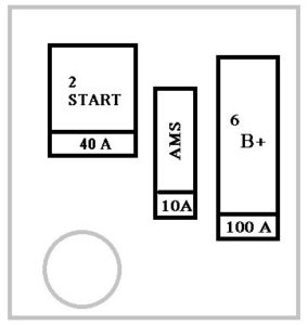
| Fuse Name | Fuse ranting [A] | Circuit protected |
| Start 2 | 40 | Metal Core Block (PCB #2) (Fuse : F8, F9, F12) |
| AMS | 10 | Battery Sensor |
| Battery 6 | 100 | Rear Smart Junction Box (Fuse : F1, F2, F3, F4, F5, F6, F7, F8, F10, F11, F13, F15, F17, F18, F19, F20) |
WARNING: Terminal and harness assignments for individual connectors will vary depending on vehicle equipment level, model, and marke

