
Maruti Suzuki Stingray – fuse box diagram
Fuse box in engine compartment
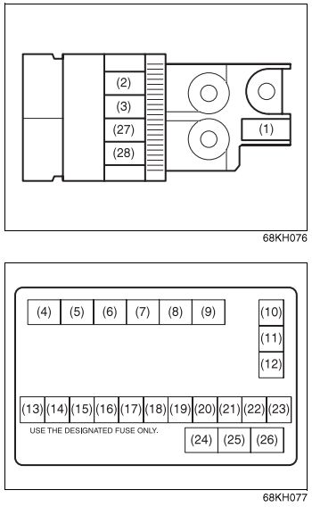
| No. |
A |
Function/component |
| 1 | 80 | All electric load |
| 2 | 50 | Dome, Tail light, Rear defogger, Door lock |
| 3 | 50 | Power window, Heater, Wiper, Ignition |
| 10 | 30 | ABS control module fuse 2 |
| 11 | 40 | Power steering |
| 12 | 40 | ABS control module fuse 1 |
| 13 | 30 | Ignition switch |
| 14 | 10 | Air compressor |
| 15 | 7.5 | CNG VLV fuse (if equipped) |
| 16 | 15 | Front fog light |
| 17 | 30 | Radiator fan |
| 18 | – | Not used |
| 19 | 15 | Headlight (Left) |
| 20 | 15 | Headlight (Right) |
| 21 | – | Not used |
| 22 | 30 | Starting motor |
| 23 | 15 | Fuel injection |
| 27 | 80 | Head light, Air compressor, Front fog light, Radiator fan |
| 28 | 80 | Power steering, ABS |
| Relay | ||
| 4 | Front fog light relay | |
| 5 | Starting motor relay | |
| 6 | CNG VLV relay (if equipped) | |
| 7 | Not used | |
| 8 | Air compressor relay | |
| 9 | Not used | |
| 24 | Radiator fan relay | |
| 25 | Fuel pump relay | |
| 26 | Main relay | |
Fuses under the dashboard
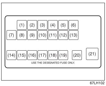
| No. |
A |
Function/component |
| 1 | 80 | All electric load |
| 2 | 50 | Dome, Tail light, Rear defogger, Door lock |
| 3 | 50 | Power window, Heater, Wiper, Ignition |
| 10 | 30 | ABS control module fuse 2 |
| 11 | 40 | Power steering |
| 12 | 40 | ABS control module fuse 1 |
| 13 | 30 | Ignition switch |
| 14 | 10 | Air compressor |
| 15 | 7.5 | CNG VLV fuse (if equipped) |
| 16 | 15 | Front fog light |
| 17 | 30 | Radiator fan |
| 18 | – | Not used |
| 19 | 15 | Headlight (Left) |
| 20 | 15 | Headlight (Right) |
| 21 | – | Not used |
| Relay | ||
| 4 | Front fog light relay | |
| 5 | Starting motor relay | |
| 6 | CNG VLV relay (if equipped) | |
| 7 | Not used | |
| 8 | Air compressor relay | |
| 9 | Not used | |
WARNING: Terminal and harness assignments for individual connectors will vary depending on vehicle equipment level, model, and market.