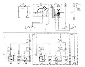
Mercedes-Benz C220 (1994 – 1996) – wiring diagrams – charging system
Year of productions: 1994, 1995, 1996
Charging system

| A1 | Instrument cluster |
| A1e5 | Generator charge indicator lamp |
| C2 | Electrolytic capacitor (generator/battery harness noise suppressor) |
| G1 | Battery |
| G2 | Generator |
| M1 | Starter |
| N3/4 | Engine control module (HFM-SFI) |
| N4/1 | EAICC/ISC control module |
| N47-2 | ETS/SPS control module |
| S2/1 | Ignition/starter switch |
| S16/4 | Starter lock-out/backup lamp switch (2nd and 3rd gear re·cognition) |
| W10 | Ground (battery) |
| Ground location without designation, component grounded directly on engine, chassis or body. | |
| X4 | Terminal block (circuit 30, left footwall) |
| X2/22 | Terminal block (circuit 30Z) (1-pole) |
| X11/18 | EA connector (chassis) |
| X12/3 | Terminal block (circuit 30/15 unfused) (3-pole) |
| X26 | Interior/engine .connector |
| X26/9 | lnterior/systef!IS connector |
| X26/25 | Engine/chassis connector (24-pole) |
| Z3/26 | Circuit 15 (unfused) connector sleeve |
WARNING: Terminal and harness assignments for individual connectors will vary depending on vehicle equipment level, model, and market.


