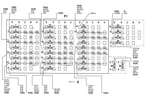
Mercedes-Benz C220 (1994 – 1996) – wiring diagrams – fuse panel
Year of productions: 1994, 1995, 1996
Fuse panel
Engine compartment fuse box

| Fuse number | Circuit | Ampere ratting [A] | Fused connection |
| 1 | 15 | 7,5 | Cockpit switch group |
| 2 | 15 | 20 | AJC pushbutton control module, Daytime running lamp control module, Fanfare horns, FAN relay module |
| 3 | 15 | 7,5 | Exterior lamp failure monitoring module, Instrument cluster |
| 4 | 56b | 7,5 | Low beam, right, Low beam, righ/ATA |
| 5 | 56b | 7,5 | Low beam, left, Low beam, left/ATA |
| 6 | 56a | 7,5 | High beam, right |
| 7 | 56a | 7,5 | High beam, left High beam indicator lamp |
| 8 | 58N | 10 | Fog Lamp |
| 9 | 30 | 30 | A/C system blower unit |
| 10 | 30 | 15 | Hazard flasher switch Clock Warning buzzer Fuel reserve indicator lamp |
| 11 | 30 | 40 | Heated rear window |
| 12 | 30 | 10 | A/C pushbutton control module Cigar lighter Seat belt warning module |
| 13 | 15R | 40 | Combination switch Headlamp flasher switch Combination relay Headlamp wiper/washer relay Windshield washer pump Wiper motor |
| 14 | 15R | 15 | Cigar lighter Glove compartment lamp Radio Rear seat heater relay |
| 15 | 58R | 15 | Cigar lighter lamp Combination relay Exterior lamp switch Illumination, licence plate Parking/tail/side marker lamps (Right) |
| 16 | 58L | 7,5 | Parking/tail/side marker lamps (Left) |
| 17 | 58NS | 7,5 | Rear fog lamp |
| 18 | 15X | 7,5 | A/C pushbutton control module Blower motor |
| 19 | — | — | — |
| 20 | 15R | 7,5 | CF control module (power windows) ESA relay module SRS MIL |
| 21 | 15R | 15 | Cellular telephone (CTEL) Heated seats Radio |
| 22 | 15 | 10 | Rear window sun shade |
| 23 | 15 | 15 | AT A control module Automatic dimming inside mirror Circuit 15 connector sleeve Front dome lamp RHR release valve RCL control m0dule |
| 24 | 15 | 15 | Backup lamp Electrically adjustable and heated outside rearview mirrors Orthopedic seat backrest (OSB) Outside mirror control switch PSE control module |
| 25 | 30 | 20 | Front HS control module |
| 26 | 30 | 15 | Cellular telephone (CTEL) Glove compartment lamp Radio |
| 27 | 30 | 15 | Central locking system Circuit 15 connector ·sleeve Front dome lamp Rear dome lamp Trunk lamp Front vanity mirror RCL control module |
| 28 | 30 | 40 | AIR relay module |
| 29 | 30 | 30 | Auxiliary fan |
| 30 | 15 | 15 | Adjustable camshaft timing solenoid EGR switchover valve Kickdown cut-out relay module Overvoltage protection relay module Purge control valve Resonance intake manifold switchover valve |
| 31 | 15 | 10 | Heated windshield washer nozzles Starter lock -out/backup lamp switch |
| 32 | 30 | 7,5 | Data link connector (DTC readout) |
| 33 | 30Z | 7,5 | Diagnostic mod~le ( OBD ll ) Cycle module (ETS/HCSiATA, A/C) |
WARNING: Terminal and harness assignments for individual connectors will vary depending on vehicle equipment level, model, and market.


