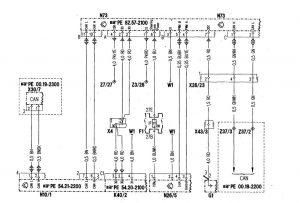
Mercedes-Benz C280 (1998) – wiring diagrams – drive authorization system
Year of productions: 1998
Drive Authorization System

| F1 | Fuse and relay box |
| F1/f27 | Fuse 27 |
| G1 | Battery |
| K40/2 | Driver-side fuse and relay module box |
| N10/1 | Signal pickup- and activation module (SAM) left front |
| N26/5 | ESC control module |
| N73 | Electronic ignition lock control module |
| W1 | Main ground (behind instrument cluster) |
| X4 | Terminal block (circuit 30, left footwall) |
| X26/23 | Engine compartmenVcockpit connector |
| X30/7 | Star-point coupler databus (CAN) tie-in connector |
| X43/3 | AEST/CL connector, circuit 30Z |
| Z3/26 | Circuit 15 (unfused) connector sleeve |
| Z7/27 | Circuit 87E connector sleeve (solder joint in harness) |
| Z37/2 | Engine CAN-Bus (low) connector sleeve |
| Z37/3 | Engine CAN-Bus (hight connector sleeve |
WARNING: Terminal and harness assignments for individual connectors will vary depending on vehicle equipment level, model, and market.


