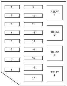
Mercury Grand Marquis (1998 – 2002) – fuse box diagram
Year of production: 1998, 1999, 2000, 2001, 2002
Passenger compartment fuse panel
The fuse panel is located below and to the left of the steering wheel by the brake pedal. Remove the panel cover to access the fuses.

| № | A | Description |
| 1 | – | Not Used |
| 2 | – | Not Used |
| 3 | – | Not Used |
| 4 | 10 | Air Bags |
| 5 | – | Not Used |
| 6 | 15 | Instrument Cluster, Warning Lamps Module, Transmission Control Switch, Lighting Control Module (LCM) |
| 7 | – | Not Used |
| 8 | 25 | Power Train Control Module (PCM) Power Relay, Coil-on -Plugs, Radio Noise Capacitator, Passive Anti-theft System (PATS) |
| 9 | – | Not Used |
| 10 | 10 | Rear Window Defrost |
| 11 | – | Not Used |
| 12 | – | Not Used |
| 13 | 5 | Radio |
| 14 | 10 | Traction Control Switch, Anti-lock Brakes (ABS), Instrument Cluster |
| 15 | 15 | Speed Control Servo, Main Light Switch Illumination, Lighting Control Module (LCM), Clock |
| 16 | 15 | Reversing lamps, Turn Signals, Shift Lock, DRL Module, EVO Steering, Electronic Day/Night Mirror |
| 17 | 30 | Wiper Motor, Wiper Control Module |
| 18 | 30 | Heater Blower Motor |
| 19 | 20 | Auxiliary Power Point |
| 20 | – | Not Used |
| 21 | 15 | Multifunction Switch, Lighting Control Module (LCM), Passive Anti-theft System (PATS) Indicator, Parking Lamps, Instrument Panel Light |
| 22 | 15 | Speed Control Servo, Hazard Lights |
| 23 | 15 | Power Windows/Door Locks, PATS, Exterior Rear View Mirrors, EATC Module, Instrument Cluster, Clock, Lighting Control Module (LCM), Interior Lamps |
| 24 | 10 | Left Hand Low Beam |
| 25 | 20 | Power Point, Cigar Lighter |
| 26 | 10 | Right Hand Low Beam |
| 27 | 25 | Lighting Control Module (LCM), Main Light Switch, Cornering Lamps, Fuel Tank Pressure Sensor |
| 28 | 20 | Power Windows |
| 29 | – | Not Used |
| 30 | – | Not Used |
| 31 | – | Not Used |
| 32 | 20 | ABS Values |
Power distribution box

The power distribution box is located in the engine compartment. The power distribution box contains high-current fuses that protect your vehicle’s main electrical systems from overloads.
| № |
A |
Description |
| 1 | 20 | Electric Fuel Pump Relay |
| 2 | 30 | Generator, Starter Relay, Fuses 15 and 18 |
| 3 | 25 | Radio, CD Changer, Subwoofer Amplifier |
| 4 | – | Not Used |
| 5 | 15 | Horn Relay |
| 6 | 20 | DRL Module |
| 7 | 20 | Power Door Locks, Power Seats, Trunk Lid Release |
| 8 | 30 | Air Suspension System |
| 9 | 50 | See Fuses 5 and 9 |
| 10 | 50 | See Fuses 1, 2, 6, 7, 10, 11, 13 and Circuit Breaker 14 |
| 11 | 50 | See Fuses 4, 8, 16 and Circuit Breaker 12 |
| 12 | 30 | PCM Power Relay, PCM |
| 13 | 50 | High Speed Cooling Fan Relay |
| 14 | 40 | Rear Window Defrost Relay, Also see Fuse 17 |
| 15 | 40 | Anti-Lock Brake Module |
| 16 | – | Not Used |
| 17 | 30 | Cooling Fan Relay |
| R1 | Rear Defrost Relay | |
| R2 | Horn Relay | |
| R3 | Cooling Fan Relay | |
| R4 | Air Suspension Pump Relay |
WARNING: Terminal and harness assignments for individual connectors will vary depending on vehicle equipment level, model, and market.


