Mercury Grand Marquis Fourth Generation (2002 – 2011) – fuse box diagram
Year of production: 2002, 2003, 2004, 2005, 2006, 2007, 2008, 2009, 2010, 2011
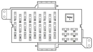
Passenger compartment fuse panel

The fuse panel is located below and to the left of the steering wheel by the brake pedal. Remove the panel cover to access the fuses.
| Fuse/relay | Ampere rating [A] | Description |
| 1 | 15 | Cluster, Lighting Control Module (Interior Lighting) |
| 2 | 10 | Ignition (ON) – Electronic Automatic Temperature Control (EATC) module, A/C mode switch (vehicles equipped with manual A/C only), A/C blower relay coil |
| 3 | 10 | EATC module |
| 4 | 10 | Ignition (ON) – Anti-lock Brake System (ABS) module, Rear Air Suspension Module (RASM), Variable Assist Power Steering (VAPS) |
| 5 | 10 | Speed control deactivation switch, Stop signal |
| 6 | 10 | Ignition (ON) – Cluster |
| 7 | 15 | LCM (Park lamps, Corner lamps) |
| 8 | 10 | LCM |
| 9 | 10 | LCM (Switch illumination) |
| 10 | 5 | Ignition (START) – Audio mute |
| 11 | 10 | Ignition (ON/ACC) – window relay coil |
| 12 | 10 | Ignition (START) – Starter relay coil, DTRS |
| 13 | 10 | Ignition (ON/ACC) – Wiper module |
| 14 | 10 | Ignition (ON) – BTSI (Floor-shift transmission) |
| 15 | 7,5 | Ignition (ON/ACC) – LCM, Door lock switch illumination, Heated seat switch illumination, Moonroof, Overhead console, Electrochromatic mirror |
| 16 | 15 | Ignition (ON) – Turn signals |
| 17 | 10 | Ignition (ON/ACC) – Audio |
| 18 | 10 | Ignition (ON) – A/C mode switch (vehicles equipped with manual A/C), Blend door, Heated seat modules |
| 19 | 10 | LCM (Left-hand low beam) |
| 20 | 10 | Ignition (ON/START) – Back-up lamps |
| 21 | 10 | LCM (Right-hand low beam) |
| 22 | 10 | Ignition (ON/START) – Restraint Control Module (RCM), Occupant Classification Sensor (OCS), Passenger Air bag Deactivation Indicator (PADI) |
| 23 | 15 | Multi-function switch (Flash-to-pass), LCM (High beams) |
| 24 | 10 | Ignition (ON/START) – Passive Anti-Theft System (PATS) module, Powertrain Control Module (PCM) relay coil, Fuel relay coil, Ignition coil relay coil |
| 25 | 10 | Autolamp/Sunload sensor, Power mirrors, Door lock switches, Mirror switch, Keypad switch, Decklid switch, Adjustable pedal switch, DDM |
| 26 | 10 | Ignition (ON/START) – Cluster, LCM, Overdrive cancel switch, Rear defroster relay coil |
| 27 | 20 | Cigar lighter, OBD II |
| 28 | 7,5 | Center High-Mounted Stop Lamp (CHMSL) |
| 29 | 15 | Audio |
| 30 | 15 | Stop lamps, MFS |
| 31 | 15 | Hazards |
| 32 | 10 | Mirror heaters, Rear defroster switch indicator |
| 33 | — | Not used |
| Relay 1 | Full ISO relay | Rear defroster |
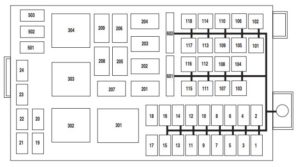
Power distribution box

The power distribution box is located in the engine compartment.
| Fuse/relay | Ampere rating [A] | Description |
| 1 | 25* | Ignition switch (Key in, RUN 1, RUN 2), Hazards |
| 2 | 25* | Ignition switch (RUN/START, RUN/ACC, START) |
| 3 | 10* | Powertrain Control Module (PCM) keep alive power |
| 4 | 20* | Fuel relay feed |
| 5 | 10* | Rear Air Suspension Module (RASM), VAPS |
| 6 | 15* | Alternator regulator |
| 7 | 30* | PCM relay feed |
| 8 | 20* | Driver’s Door Module (DDM) |
| 9 | 15* | Ignition coil relay feed |
| 10 | 20* | Horn relay feed |
| 11 | 15* | A/C clutch relay feed |
| 12 | 25* | Audio |
| 13 | 20* | Instrument panel power point |
| 14 | 20* | Stop lamp switch |
| 15 | 20* | Heated seats |
| 16 | 15* | Foglamps |
| 17 | — | Not used |
| 18 | — | Not used |
| 19 | 15* | Injectors |
| 20 | 15* | PCM, Mass Air Flow (MAF) sensor, IAT |
| 21 | 15* | Powertrain loads and sensors, A/C clutch relay coil |
| 22 | — | Not used |
| 23 | — | Not used |
| 24 | — | Not used |
| 101 | 40** | Blower relay feed |
| 102 | 50** | Cooling fan |
| 103 | 50** | Instrument panel (I/P) fuse box feed #1 (I/P fuses 19, 21, 23, 25 and 27) |
| 104 | 40** | Instrument panel (I/P) fuse box feed #2 (I/P fuses 1, 3, 5, 7, 8 and 9) |
| 105 | 30** | Starter relay feed |
| 106 | 40** | Anti-lock Brake System (ABS) module (Pump) |
| 107 | 40** | Rear defroster relay feed |
| 108 | 20** | Moonroof |
| 109 | 20** | ABS module (Valves) |
| 110 | 30** | Wiper module |
| 111 | — | Not used |
| 112 | 30** | Air suspension compressor |
| 113 | — | Not used |
| 114 | — | Not used |
| 115 | — | Not used |
| 116 | — | Not used |
| 117 | — | Not used |
| 118 | — | Not used |
| 201 | 1⁄2 ISO relay | A/C clutch |
| 202 | — | Not used |
| 203 | 1⁄2 ISO relay | Ignition coil |
| 204 | 1⁄2 ISO relay | PCM |
| 205 | 1⁄2 ISO relay | Fog lamps |
| 206 | 1⁄2 ISO relay | Fuel |
| 207 | — | Not used |
| 208 | — | Not used |
| 209 | 1⁄2 ISO relay | Horn |
| 301 | Full ISO relay | Starter |
| 302 | Full ISO relay | Air compressor |
| 303 | Full ISO relay | Blower |
| 304 | Full ISO relay | Power windows relay (RUN/ACC) |
| 501 | Diode | A/C clutch |
| 502 | Diode | PCM |
| 503 | Diode | Horn, Door latch |
| 601 | 20A Circuit breaker | Power seats, Lumbar |
| 602 | 20A Circuit breaker | Power windows relay feed (RUN/ACC) |
| * Mini fuse ** Cartridge fuse | ||
WARNING: Terminal and harness assignments for individual connectors will vary depending on vehicle equipment level, model, and market.


